Add Audio/Video In/Out and TV to your Nav for ~$300
DISCLAIMER: Use this page at your own risk! (enough
said)
NOTE: I was dissatisfied with the PC's video quality and I no
longer have this in my car.
See my Display v2 page to see the before and after
comparison
Introduction
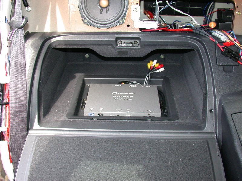
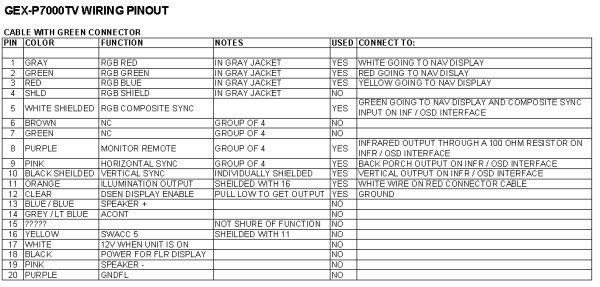
This page shows how to splice a "Pioneer GEX-P7000TV Hide-Away TV Tuner" in to
almost any video screen that uses RGBS signals.
"Pioneer GEX-P7000TV Hide-Away TV Tuner" is too hard to say, so let's just call
it the GEX.
There are two ways to get TV and A/V inputs in to most existing Nav systems:
- You can buy a complete assembly from:
- You can build the complete assembly yourself for $300:
$240
for the Pioneer GEX-P7000TV (these
are becoming hard to find)
$43 in parts from DigiKey and RadioShack (all listed below)
...plus a good VGA cable, plus shipping (as always)
You might also want to go ahead and get the AN-G3 antennas for the GEX (cost
is around $70).
This page is NOT intended to harm video-nav's or avelectronics' business; in fact, it may be
doing the opposite! If you are not a "Do-It-Yourself"'er then I definitely suggest that you buy
avelectronics' or video-nav's solution! AVElectonics looks like
the way to go. Their solution is less expensive than Video-Nav's, has 3
A/V inputs, 2 A/V outputs, includes antennas, and has a built in reverse camera
feature (camera sold separately).
The GEX solution I show below only has 2 A/V inputs, 1 A/V output, no
"reverse" feature, and the antennas add an extra $70.
If you are a DIY'er then I still recommend that you build it
yourself; when you are done you will realize how simple and fun it really was!

The wiring
schematics of this solution are, to my knowledge, neither trademarked, nor copyrighted,
nor patented; the
circuit is public domain knowledge on some
message
boards and web sites.
The solution exists independently of video-nav; video-nav just happens to be trying
to sell their nice solution for a profit. Kudos to them for bringing a
niche solution like this to the
market, and good luck to them in their business. Your time is worth money, and this project could take you several
days (or weeks) to complete. Again, it may be worth $525-$600 of your time
to just buy the complete solution from someone else.
I in no way claim originality or full credit for this idea. The information
for this idea is scattered on several different web sites making it hard [for
me] to grasp. This page is a consolidation of everything I found useful.
The following sites were used for information:
The best site by far is Boom's, but he is missing a few optimizations that
were suggested on the boards, could be a little more thorough/detailed, and ignores some grounding
issues. I cannot find a way to get in touch with him to ask
him to update his page, so this is another justification for posting his info
here.
Wonderer369 deserves a ton of credit for his help. As far as I know he
was the first person to make this mod in a Nissan/Infiniti vehicle, and just
seeing his setup work was encouragement enough to help me persist through this
project. He answered
every single email I sent him asking about the GEX. Wonderer is a great guy,
and he has a sweet ride too! :)
A FEW NOTES BEFORE WE GET STARTED:
- I apologize in advance if my directions are a little exhaustive; They should
hopefully save you from having many questions.
- I am a big fan of soldering; feel free to use crimp connectors if you
want (at your own risk...they can vibrate/yank free)
- Keep in mind that these steps are intended for the 2003 Nissan 350Z (and
possibly any Nissan/Infiniti with navigation).
The directions are probably
still useful on other vehicles with RGBS screens, but you will have to
determine any deviations yourself.
- Prepare your Nav
system's wiring for the GEX
Basically, we are going to splice a VGA cable in to your existing the wiring harness
so that it can
more easily be worked with.
This has the benefit of minimal impact on the original wiring and using nice
shielded cable.
ETA: Approximately 2 hours
- Prepare your GEX's
wiring for the Nav system
Basically, we are going to convert the GEX's proprietary wire to VGA
connectors (to mate with the ones installed in Step #1).
ETA: Approximately 2 hours
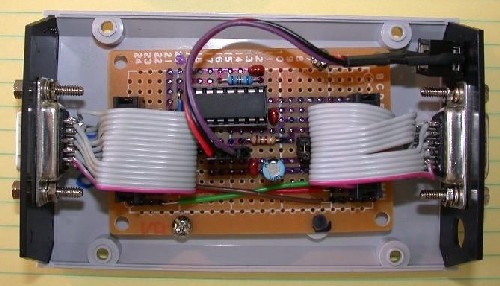
- Building the Infrared/On Screen Display (IR/OSD) device
This is the only slightly complicated part of this whole system, however it is
actually quite simple and very fun!
ETA: 1 week for parts, 3-12 hours to build (depending on your
soldering/electronic skills)
- Wire it all together
ETA: Approximately 1 hour
Reference
|
|
 |
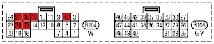
(looking at the front of the Nav connector) |
|
| 20 |
18 |
16 |
14 |
12 |
10 |
8 |
6 |
4 |
2 |
| 19 |
17 |
* |
13 |
11 |
9 |
7 |
5 |
3 |
1 |
|
 |
| (looking at the front of the GEX connector) |
|
|
| Function |
Nav CPU |
VGA F/M |
GEX Red |
G
E
X
-
P
7
0
0
0
T
V |
GEX Green |
VGA F/M |
Nav Screen |
| RGBS Red |
18 |
Black |
1 |
1 |
Quad-Axial Gray |
1 |
Quad-Axial Gray |
1 |
I
R
/
O
S
D |
18 |
Black |
| RGBS Green |
21 |
White |
2 |
2 |
Quad-Axial Green |
2 |
Quad-Axial Green |
2 |
21 |
White |
| RGBS Blue |
15 |
Red |
3 |
3 |
Quad-Axial Red |
3 |
Quad-Axial Red |
3 |
15 |
Red |
| RGBS Ground |
17 |
Black/White |
5 & Hood |
4 |
Quad-Axial Shield |
4 |
Quad-Axial Shield |
5 & Hood |
17 |
Black/White |
| RGBS Sync |
20 |
Pink |
15 |
5 |
White Coaxial |
5 |
White Coaxial |
15 |
20 |
Pink |
| +12V ACC |
6 |
Light Green |
11 |
17 |
White |
N/A |
N/A |
| +5V |
N/A |
16 |
Yellow |
9 |
| DISP ON |
12 |
Clear |
10 |
| IR Remote |
8 |
Small Purple |
12 |
| H-Sync |
9 |
Small Pink |
13 |
| V-Sync |
10 |
Small Black |
14 |
| |
|
|
All other wires... |
|
All other wires... |
|
|
|
|
| Parts and Tools |
Quantity |
Cost |
High Quality Shielded VGA Extension Cable (Male and Female
connectors)
NOTE: We will be cutting it in half, so I recommend 10', but any length
will do |
10' |
$10 |
| 26-22GA Wire Tap In Connector (@ HomeDepot?) |
1 |
? |
| 22-18GA Heat Shrink (@ RadioShack?) |
2' |
$2 |
| 26-22GA Crimp On Butt Connectors (@ RadioShack?) |
10 |
? |
| Low-Watt Soldering Iron (20W is enough for what we are doing) |
|
|
| 26-16GA Wire Cutter and Stripper |
|
|
| Electrical Tape |
|
|
| Extension Cord |
|
|
| A thin block of wood (to solder against INSIDE THE CAR) |
|
|
Steps:
- Cut the VGA cable in half. Yes, cut it in half!
Again, I recommend a 10' cable, but any length will do (obviously, the
shorter the better)
- On the female VGA cable assembly, carefully strip off about 4-6 inches of the outer insulation leaving
the shielding intact
- Fold the shielding back, snip the foil at the base and peel it off
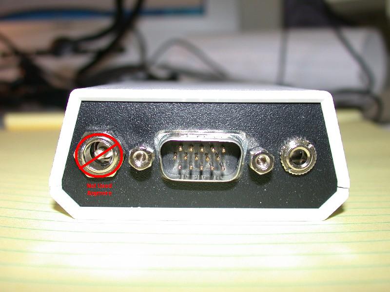
- Find the 6 wires for pins 1, 2, 3, 11, 15, and Ground/Shield (use a
multi-meter continuity check)
Pins 1, 2, and 3 should be separate shielded coaxial cable
Ground/Shield should have a dedicated fibrous wire attached to the shielding
- Cut all of the other wires off (to get them out of the way), they won't
be used at all.
None of these wires will be carrying a signal, so there is no concern that
they will short circuit.
- Carefully strip off about half off the outer insulation on wires 1, 2,
and 3 leaving the shielding intact.
- Fold the shielding back.
- Carefully strip off enough of the dielectric/insulation for the wire to fit in the
butt connector (about 1/4").
- Cut wires 11, 15 and Ground/Shield so that they match the length of wires 1,
2, and 3.
- If your 26-22GA butt connectors have insulation on them, take the insulation off
now.
- Solder 5 butt connectors to the tips of wires 1, 2, 3, 15, and
Ground/Shield (NOT wire 11).
Do this quickly enough so that the wire does not get too hot and start to melt the
dielectric/insulation.
I recommend filling the butt connector with solder first, then reheat it and
slide the wire in.
- Cut 8 3" segments of heat shrink and slide them all the way to
the back of each of the signal wires (not ground/shield).
DO NOT SHRINK THEM YET!
- Repeat steps 2 thru 12 on the male VGA cable assembly.
- Get access to your Nav unit's main wiring harness and pop out it's first anchor point
on the chassis.
This will make accessing the harness much easier.
- Carefully slit the heat shrink back about 6-8", cut it off and save it
(we will be putting it back).
Be VERY careful not to nick/cut any wires (I did this myself).
If you do nick/cut a wire then no big deal; repair it with a butt connector
and heat shrink.
- Now for the scary (and sadistically fun) part: Cut the 5 Nav wires mentioned in the pinout
reference table (by wire color).
The wires should be logically grouped in to 3 groups: RGB, Ground, and Sync.
Cut them about halfway between the connector and the cut-back insulation
(3-4 inches).
DO THIS AT YOUR OWN RISK! This probably voids your Nav's warranty.
- Carefully strip off enough insulation for the wires to fit in the butt
connector.
- Run an extension cord to your car and warm up your soldering iron.
You are about to begin soldering INSIDE your car; be ULTRA careful not to
drop the iron inside your car!
DO THIS AT YOUR OWN RISK!
- Using the pinout reference table above, solder the female VGA cable
assembly to the wires that lead to the Nav CPU.
Again, pay attention that the wire does not get too hot and start to melt
the diaelectic/insulation or the heat shrink.
- Slide each of the heat shrinks over the butt connectors.
DO NOT SHRINK THEM YET!
- Repeat steps 19 and 20 for the male VGA cable assembly to the
wires that lead to the Nav Display.
- On the female VGA cable assembly (the one connected to the Nav
CPU), connect wire 11 to the 12V ACC wire (#6, Light Green)
with a wire tap.
Remember, we will only need to "tap" in to this wire; we do not want to cut
it!
Alternatively, you could just connect any ACC voltage line to wire 11 (this
is what I did).
- Now is the ideal time to test if the wiring is working OK.
If you find a problem then you won't have to undo any of the below steps.
Connect the female and male ends of the VGA cables.
Start your Nav system and check that everything is working like it used to
(especially the screen).
If everything looks good then proceed with the next steps.
If there is a problem then you are on your own! ;)
- Shrink the heat shrink on the butt connectors.
- Unfold the RGB wire shielding over the butt connectors.
- Unfold the main shielding over both cable assemblies.
For our purposes we prefer that all of the ground/shielding wires
to touch each other.
- Wrap a few turns of electrical tape over each cable assembly.
- Run the cable assemblies so that they run in opposing directions
(minimizing strain and bend).
- Replace the heat shrink that you took off in Step 15 and wrap the hell
out of it with electrical tape!
- Your Nav wiring is now both self sufficient and prepared for interfacing with
a modified [see below] GEX-P7000TV!
I would suggest labeling both VGA connectors with "RGBS,
NOT VGA".
I would not expect anything good to happen if you plug the male
connector into a VGA card or the female into a monitor.
Steps:
- Cut the GEX's Green/Red RGB cable in half. Yes, cut it in half!
- Carefully strip off 3"-4" of the outer insulation.
NOTE:
Cut carefully; the cables inside are very fine and are not very well protected.
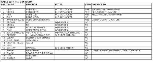
- Using the Wiring Pinout Summary as
a reference...
- Wire the Female VGA connector to the cable with the Green connector.
- Wire the Male VGA connector to the cable with the Red connector.
Be careful to cut all of the "unused" wires such that they cannot short
out with either Ground or with each other.
Be sure to keep Pin 5, the Ground/Shielding, and the Hood all in contact.
- As with the Nav wiring, I would suggest labeling both VGA connectors with "RGBS,
NOT VGA".
I would not expect anything good to happen if you plug the male
connector into a VGA card or the female into a monitor.
Your GEX is almost ready to communicate with your Nav system, but we are
missing a few last things.
- The GEX itself has no IR eye for the remote, so we need to add one and
send the signal back to the GEX.
NOTE: There is a mysteriously useful looking "V-Sel Info Terminal" input on the GEX.
Perhaps this could be used
to eliminate the need for the IR eye?
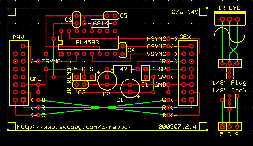
- The GEX's OSD needs to know the H-Sync and V-Sync of the video
signal so that it can overlay a menu.
An
Intersil/Elantec EL4583 Integrated Circuit will be used to extract these
signals from the Composite Sync.
- The GEX needs the "DISPLAY ON" (Clear) wire jumped to Ground so that it thinks a Display is connected.
This is accomplished by the J1 jumper in the below schematic.
NOTE: Using a jumper/shunt to accomplish this is completely optional; you
may just hardwire this with a simple trace/wire.
- The RGBS wires from the GEX need to be routed out to the Nav Display.
Thus the reason we need to build the following IR/OSD device.
|
|
 |
 |
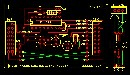
schematic |
 |
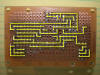 |
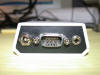
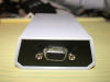
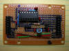
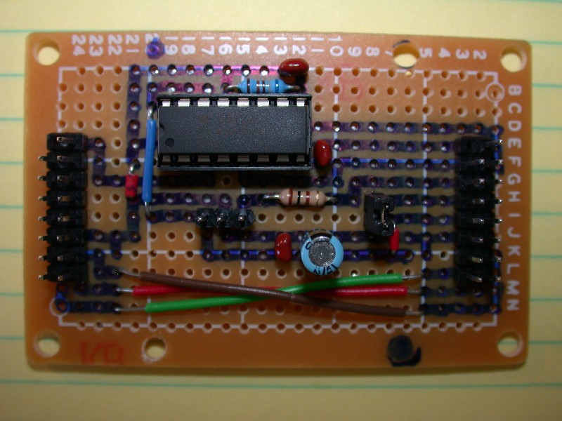
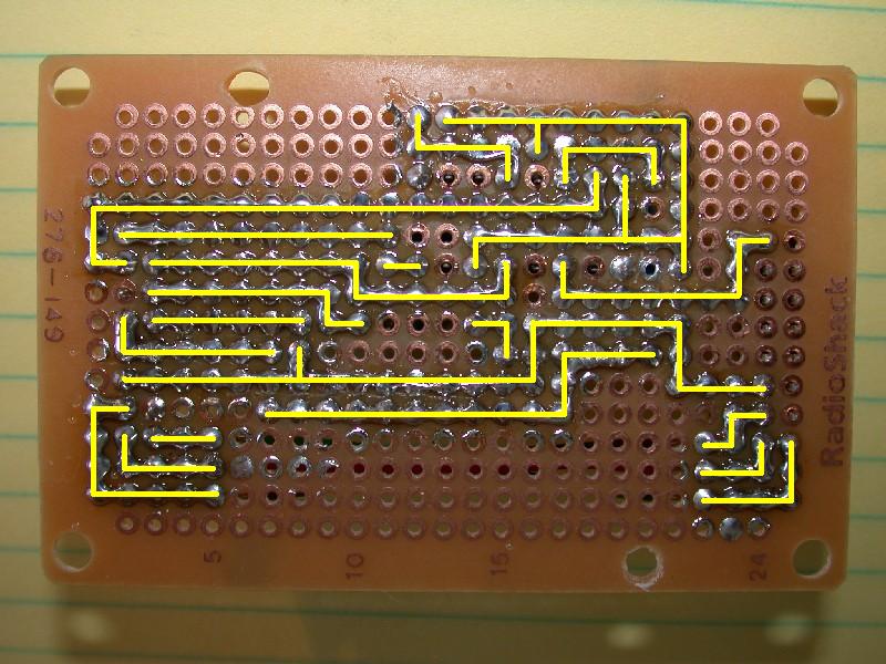
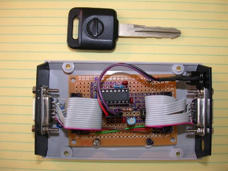
NOTE: Build this circuit
according to the schematic.
The pictures are of a previous version and should only be used as a
general guide. |
Parts List
NOTE: "Part ID" indicates the component
shown in the
circuit schematic
|
|
| Quantity |
Part Number |
Description |
Part ID |
Unit Price
USD |
Extended Price
USD |
1 |
SRA21B-ND |
BOX A SERIES BLK (2.6X4.25X1.12) |
ENCLOSURE |
3.65000 |
$3.65 |
2 |
SR2005-DB9B-ND |
END PANEL W/DB9 FOR A-21 BLK |
2.77000 |
$5.54 |
1 |
S2012-36-ND |
CONN HEADER .100 DUAL STR 72POS |
GEX, NAV |
1.85000 |
$1.85 |
1 |
S1012-36-ND |
CONN HEADER .100 SINGL STR 36POS |
IR REMOTE

OPTIONAL J1 |
1.03000 |
$1.03 |
1 |
C3AAT-1606M-ND |
IDC CABLE - CSC16T/R002/CSC16T |
|
3.30000 |
$3.30 |
1 |
425-1175-5-ND |
RECEIVER REMOTE CTRL SIDE 38KHZ |
IR EYE |
2.25000 |
$2.25 |
2 |
P5164-ND |
CAP 47UF 35V ALUM LYTIC RADIAL |
C1,C2 |
0.28000 |
$0.56 |
4 |
399-2127-ND |
CAP .1UF 50V 20% CER RADIAL |
C3,C4,C5,C6 |
0.16000 |
$0.64 |
5 |
681KXBK-ND |
RES 681K OHM 1/4W 1% METAL FILM |
681K |
0.10800 |
$0.54 |
5 |
47QBK-ND |
RES 47 OHM 1/4W 5% CARBON FILM |
47 |
0.05600 |
$0.28 |
1 |
ZXFV4583N16CT-ND |
IC SEPARATOR VIDEO SYNC 16-SOIC |
EL4583 |
7.98000 |
$7.98 |
1 |
A726-ND |
SOCKET ADPTR SOIC/16PIN .300DIP |
6.97000 |
$6.97 |
4 |
160-15F-ND |
ASSY SCREWLOCK 4-40 FEMALE .520" |
|
0.55000 |
$2.20 |
NOTE: You have to complain to
DigiKey in order to get the 1st two prices I mention here.
"Request a quote" through their web page saying the following:
Mouser.com offers a much lower "1 unit" price on
the following items:
| Item |
DigiKey
Price |
Mouser
Price |
| SRA21B |
$6.33 |
$3.65 |
| SR2005-DB9B |
$4.76 |
$2.77 |
Could you please match or beat their price?
Thank you.
They will send you an email back with a price match that should save
you $6.66. |
|
Subtotal |
$36.79 |
| Handling |
$0.00 |
| Shipping |
unknown |
| Sales Tax |
unknown |
| |
| |
| |
| |
| |
| |
| |
| |
| |
| |
|
| Part ID |
Description |
RadioShack Part # |
| |
1/8" Stereo Phono Cable, 12' |
? |
| |
1/8" Stereo (3 conductor) Phono Jack, Panel Mount |
? |
| 22K |
22KΩ Resistor 1/4W 5% Carbon Film |
271-312 |
| 82K |
82KΩ Resistor 1/4W 5% Carbon Film |
-
22K and 82K resistors may be added for filtering and
signal detection.
Read the EL4583 manual for more info and decide if you want these or
not.
I did NOT add these. For an example of how to use them
go here.
-
For the IR Receiver Module:
-
Cut one end off of the 1/8" cable
-
Solder the 1/8" cable to the IR module
(Wire/pin matchings do NOT matter here)
-
Solder the Header wires to the Phono Jack
(Here is where wire/pin matchings DO matter)
-
Mount the IR "Eye" somewhere visible, but
inconspicuous, in
your car
-
Unlisted parts that I stole from my "parts" bin:
-
Mounting screws for PC Board
-
4-wire header (for IR connecting to the module)
Use an old CD-ROM Audio connector
-
Miscellaneous Wire and Solder
I had this kit laying around:
276-173
I hope you know where to find solder.
-
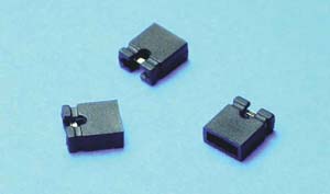
OPTIONAL: Jumper Shunt for
OPTIONAL J1
Use one from an old motherboard
|
|
IR/OSD Grand Total: $42.16 + Tax + Shipping
+ a few miscellaneous parts.
In all, well less than $60 in parts. |
|
| |
| NOTE: Do NOT forget to connect a jumper to J1! |
08/18/03: I have had my IR/OSD circuit in my car for over 3 weeks now, and
my only problem to date is that every 20 to 30 times that I start my car the video sync
doesn't always...well..."sync". The problem is quickly
noticeable and easily solved by rebooting the PC before it has a
chance to get far in to the "boot" process. I, personally, can live with this. You may find it worth your time to experiment with the
optional resistors that I mention.
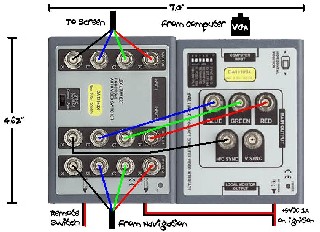
This is very easy because everything is modular; just follow the below
diagram:
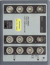
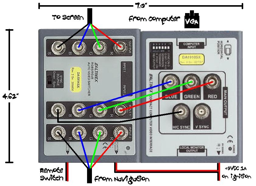
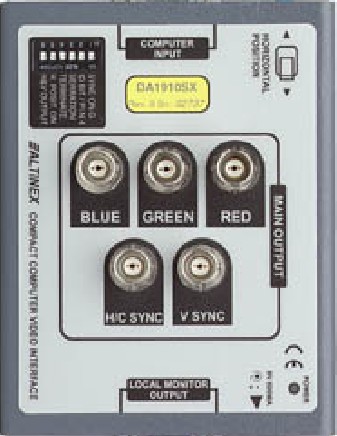
Altinex DA1910SX and DA1914SX
 |
  |
6/7/2003: I finally gave up on this idea. It was a valiant attempt and
would have been the perfect lightweight solution if only the DA1910SX was a
Scan-Converter. Alas, it is not, it merely combines a few sync signals,
but does nothing to make the signal NTSC compatible. If I could get my
computer to output 30Hz interlaced video that might work, but the CLE266 chip on
a VIA ITX motherboard apparently I
cannot (even using PowerStrip). Another bonus to the GEX solution [above] is the addition of a TV
tuner and second video source. That, and the fact that people have proven
that the GEX solution works, sold me. Maybe one day I will stumble across an
inexpensive high-quality scan converter (or an ITX motherboard that can output
VGA at NTSC scan rates) and could perhaps visit this solution again.
Ah, goodbye fair Altinex devices, you were fun while you lasted.
4/26/2003: These beauties were bought on eBay last week, for a total of $82, and
they should get
here soon. Once they actually show up I plan to crack them open and see
their innards. I hate having those BNC jumpers between the two units, so I
may look in to combining these guys into a single case with more direct wiring.
- Q: How can I do a similar thing using an XBOX [instead of
the GEX]?
A: I HAVE NO IDEA IF THIS WILL ACTUALLY WORK, but I would suggest getting an Altinex DA1914SX and
trying the following:
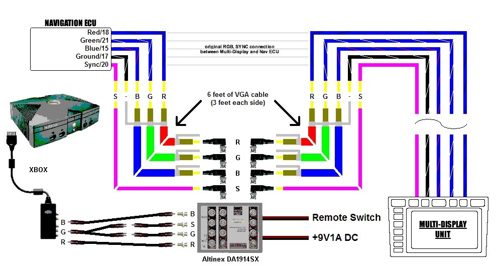
Here are the parts you will need:
- 4 x RCA to BNC adapters - RadioShack Part #:
278-303
- 1 x RCA "Y" splitter - RadioShack Part #:
42-2536
- 8 x BNC adapters - RadioShack Part #:
278-126
- 1 x 6' VGA cable (cut in half and cut the tips off)
- 1 x On/Off toggle switch ("Remote Switch")
(I put mine in the empty seat warmer button)
- 1 x 12V to 9V1A power adapter - RadioShack Part #:
273-1863
- 2 x RadioShack AdaptaPlug "N" tip - RadioShack Part #:
273-1717
(one for Remote Switch, one for (9V1A power)
- Some RCA cables
- Some wire for the 9V1A power and remote switch
- Crimp/Solder etc (typical electronic wiring equipment)
- Q: I am not very good at electronics. I don't think I can do this to
my car. Can you help me?
A: I, the dude that wrote this page, am not that great at electronics either.
If you have ever built legos or hooked up a home stereo/TV then you are pretty
much qualified to do this.
Building the IR/OSD circuit is not much more complicated than building legos.
Think of the circuit as grown up legos.
Running the wiring is not much more complicated than hooking up your home
stereo/TV.
You CAN do this.
Yes, it may be a challenge, but it is fun (in a sick sort of way ;)).
No, I will not physically help you (but I will answer your questions via
email).
- Q: My car came with navigation. I want to replace the navigation CPU
but keep the screen. Can I do this?
A: That is the whole reason for this page!
To be honest, you may not be impressed with the results though.
Two main problems:
1) Poor video quality due to a required video conversion if your replacement
unit does not output RGBS video signals.
2) Lack of a touch screen
These reasons alone were enough for me rip this project out of my car.
The results would have been acceptable if I was not dealing with a Windows XP
desktop.
You would be OK as long as you don't have to read any small fonts.
Perhaps one day I will write a new UI shell for Windows XP with big fonts and
big buttons.
Only after then would I re-consider putting the GEX back in my car.
- Q: My car came with navigation. I want to keep the navigation CPU
but replace the screen. Can I do this?
A: Not easily, and not cheaply, which is why I gave up on trying to do this.
Let me explain a few things first...bare with me:
Your navigation CPU and screen/display were [obviously/hopefully] designed to
work together.
Most car navigation systems use RGBS "Component" video signals.
Just to confuse things, let me explain the two types of "Component Video".
1) YUV - This is TRUE Component Video, but very few home televisions
[in America] actually support YUV.
YUV can also be referred to as "YIQ", "Y-RY-BY", or "Y-Cb-Cr".
The Y represents "Luminance" (brightness), and the UV represents "Chrominance"
(color).
Thus why YUV is also referred to as "Luminance Chrominance", or "Brightness
Color".
Chances are that your car's navigation system does NOT use YUV.
2) RGB - This is NOT true Component Video, but most [American]
televisions support RGB which they mistakenly called "Component Video".
RGB means "Red, Green, Blue", which are the 3 primary colors of light.
RGB can be transmitted as either RGBHV (5 signal wires + ground), RGBS (4
signal wires + ground), or RGsB (3 signal wires + ground).
RGBHV means "Red, Green, Blue, Horizontal-Sync, Vertical-Sync".
RGBS means "Red, Green, Blue, [Composite-]Sync" (Composite-Sync combines
H-Sync and V-Sync in to one signal).
RGsB means "Red, Green, Blue, [Composite-]Sync-On-Green"
(Sync-On-Green combines Green and Composite-Sync in to one signal).
Chances are that your car's navigation system does use RGBS.
The two Component Video formats are not directly compatible; you must
convert from one to the other.
If you are curious for more info on how YUV and RGB are related you can read these:
http://www.michaeldvd.com.au/Articles/VideoConnectors/VideoConnectors.asp
http://www.zerocut.com/tech/vid_img.htm
ftp://www.zerocut.com/PC_files/422-RGB Conversions.pdf
So, let us ASSuME that your car carries RGBS video signals.
The main problem with replacing your navigation's existing screen/display is
that very few commercially available 7" displays (Lilliput, Xenarc, etc)
accept RGBS video!
They tend to only accept two types of video:
1) "VGA" - One of the MOST desirable video signals.
2) "Composite" - One of the LEAST desirable video signals.
If you can find a 7" display that accepts RGBS input then AWESOME!
If not then you will need a way to convert your navigation's RGBS output signal to your
screen's VGA or Composite input signal.
Converting RGBS to Composite is relatively cheap and easy, but the image
quality is horrible!
Converting RGBS to VGA is called a "scan conversion" and is quite complex and
expensive.
It is VERY hard to find a "reasonably priced 12V powered RGBS to VGA
scan converter".
It is for this exact reason that I gave up trying to find one of these (in
Summer 2003) and ended up replacing my entire NAV system.
If you chose to try this I would be very interested in hearing about your
results.
- Q: Why did you give up on this project?
A: Two reasons:
1) Poor video quality (of my Windows XP desktop)
2) No touch screen
Visits Since 10/2/2004:


